EDT SHOW FRAMER CONFIG <ALL, BRI, PRI, T1D4, DPNSS>
EDT SHOW FRAMER REGS <ALL, BRI, PRI, T1D4, DPNSS>
EDT SHOW FRAMER STATS <ALL, BRI PRI, T1D4, DPNSS>
EDT SHOW LINK CONFIG <ALL, BRI, PRI, or T1D4, DPNSS>
EDT SHOW LINK STATUS <ALL, BRI, PRI, or T1D4, DPNSS>
EDT SHOW VDSU <TABLE, NETSYNC, CHANNELS, ALARMS, STATS, or DBFLAGS>
None.
Defines the abbreviations that appear in output of the Framer statistics.
2005-03-11 12:01:55
EDT Show Framer Config <ALL, BRI, PRI, T1D4, DPNSS>
DESCRIPTION:
FMSL - Framing Mode Select (1,0x10)
TACW - Transmit Alarm Control Word (1,0x11)
SGCW - Signalling Control Word (1,0x14)
CLCW - Coding and Loopback Control Word (1,0x15)
LIUC - LIU Control Word (1,0x1F)
CFCW - Configuration Control Word (2,0x10)
CTxP - Custom Tx Pulse Enable (2,0x11)
2005-03-11 12:01:55
EDT Show Framer Status <ALL, BRI, PRI, T1D4,
DPNSS>
DESCRIPTION:
ALW1 - Alarm Status Word (3,0x11)
SYNC - Synchronization Status Word (3,0x10)
OVFL - Overflow Reporting Latch (3,0x1F)
MFSC - Multiframe out of sync counter (4,0x15)
PSW1 - Most Significant Phase Status Word (3,0x13)
PSW2 - Least Significant Phase Status Word (3,0x14)
FRBC - Framing Bit Counter (4,0x13)
RBOM - Receive Bit Oriented Message (4,0x13)
RSSW - Receive Sig Status Word (3,0x16)
OCFC - Out-of-frame/Change FR align. counter (4,0x14)
ALRM - Alarm Reporting Latch (4,0x12)
BPV1 - Most Significant Bi-pol. Violation Error (4,0x16)
BPV2 - Least Significant Bi-pol. Violation Error (4,0x17)
CRC1 - Most Significant CRC4/CRC6 counter (4,0x18)
CRC2 - Least Significant CRC4/CRC6 counter (4,0x19)
<ALL, BRI, PRI, T1D4, DPNSS>
Displays the framer's configuration.
2004-11-18 10:35:57
Logical link number: 1
Framer Mode =
T1 - Pattern = D4 - Signal Mode = CAS
Slot = 0 - Number =
0 - Address =
0x20000000
NT/LT Mode: S/W controlled -> LT mode
Line Impedence = 100
Current Link Status = NO ALARM
D Channel Status support not requested
Remote Loopback = DISABLED
- RM Counter (0 - 50) 0
Interrupts Connected = true and Enabled
Yellow Alrm Bit Mask = 0x80 - LOSS Alarm Bit Mask = 0xc0
TDM Stream =
0
Client Instance = 0x7819460
Callback = 0x3f85cf0 - Enabled
Client Instance = 0x4177edc
Callback = 0x3f30e70 - Disabled
<ALL, BRI, PRI, T1D4, DPNSS>
Displays the framer's register.
2004-11-18 10:37:37
Logical link number: 1
Page# 00 01 02 03 04 05 06 07 08 09 0a 0b 0c 0d 0e 0f
1 20 10 0 0
b0 a0 0 f 0
0 4 59
20 0 8 0
2 0 88 0 0
20 20 20 20 20
20 20 20 62 62
6 2
3 1 0 80 80
ff 0 8
40 11 11 11 11
0 0 63
af
4 0 c6 cc 0 0
0 0
0 0
0 0
0 0
0 0
0
CPLD -> LED<21> CTL<03> TIM<00> IRQ<03> NTLT<27> TEST<00> IMP<0c>
<ALL, BRI, PRI, T1D4, DPNSS>
Displays statistics for the framer.
System Response Example:
2004-11-18 10:39:45
Link FMSL TACW SGCW CLCW LIUC CFCW CTxP
1: 0x20 0x10 0xB0 0xA0 0x 0 0x 0 0x88
Link ALW1 SYNC OVFL MFSC PSW1 PSW2 FRBC RBOM RSSW OCFC ALRM BPV1 BPV2 CRC1
CRC2
1: 0x00 0x01 0x02 0x00 0x20 0x06 0x00 0x00
0x08 0x00 0x00 0x00 0x00
0x00 0x00
<ALL, BRI, PRI, T1D4, DPNSS>
Displays link configuration.
System Response Example:
2004-11-18 10:41:47
Logical link number: 1
ESM link number: 1
Descriptor ID: 1
Protocol: T1D4
Termination Mode: LT
Line Coding: B8ZS_T1_LINE_CODING
Framing Format: D4_FRAME
Operation Mode: DSX1-T1
T1 line_length: 0-133
feet
<ALL, BRI, PRI, T1D4, DPNSS>
Displays link status.
System Response Example:
2004-11-18 10:42:52
Logical link number: 1
TSP Link Status: NearEnd_FarEnd_UNKNOWN
TSP Layer 1 Status: GREEN
TSP Layer 2 Status: DOWN
Interface Activated: TRUE
None.
Displays the number that is assigned to the link in the system administration tool, the physical location identifier (PLID) of the link, the type of link, the descriptor that is assigned to the link, and identifies whether or not the link is operating.
System Response Example:
2004-11-18 10:43:59
ESM Link: 1
SP PLID: 6
1 2 1
SP Type: T1D4
Link Descriptor: 1
Running: yes
2004-11-18 10:43:59
ESM Link: 2
SP PLID: 6
1 3 1
SP Type: T1D4
Link Descriptor: 3
Running: yes
2004-11-18 10:43:59
ESM Link: 9
SP PLID: 7
1 2 1
SP Type: BRI
Link Descriptor: 7
Running: yes
None
Displays the link number, usage, VDSU Object, Protocol Type, interface type , link descriptor and integrated digital access.
System Response Example:
2004-11-18 10:48:28
-------------------------------------------------------------------------
VDSU Object Table
----+-------+----------+----------+----------+-----------+----------
Lnk | InUse | VDSU |
Protocol | Intrface | Link |
Integrat
Num | | Object
| Value |
Type | Descript
| Dig Acc
----+-------+----------+----------+----------+-----------+----------
001 | true | 075B4BA8 | 00000000 | 00000058 | 00000001
| 00000002
002 | true | 074B3630 | 00000000 | 00000058 | 00000003
| 00000002
003 | true | 073E8E10 | 00000007 | 00000077 | 00000007
| 00000009
004 | true | 00000000 | 00000000 | 00000077 | -00000001
| 00000000
005 | false | 00000000 | 00000000 | 00000000 | -00000001 | 00000000
006 | false | 00000000 | 00000000 | 00000000 | -00000001 | 00000000
007 | false | 00000000 | 00000000 | 00000000 | -00000001 | 00000000
008 | false | 00000000 | 00000000 | 00000000 | -00000001 | 00000000
<cab> <shelf> <slot> <port>
Displays the netsync status of the link.
System Response Example:
2004-11-18 10:49:40
Link 0 Hybrid 0 netsync parameters:
netsync state: LTA,
interval count: 54, sample reset: FALSE
current enabled link: 0 previously
enabled link: -1
current LTA: fffffff7
last LTA sent to 2k: fffffff6
request timer: NOT
SET, bad samples: 0, link values okay: yes
single hits: 0
phase shifts: 0
unstable: 0
current re-sync count: 0 current sample index:
5
LINK 0 Hybrid 0 sample data:
103 103 103 103 104 104 103 103 103 103 103 103 103 103 104 104
Jitter data: accum=1, max=1, min=-1, threshold=5
Samples above were normal.
Link 0 hybrid 0 enable information: LTA
<cab> <shelf> <slot> <port>
Displays the state of each channel.
2004-11-18 10:50:36
AFCCHAN CHANNEL STATES
channel 0 1 2
3 4 5
6 7 8
9 10 11 12 13 14 15 16 17 18 19 20 21 22 23
link 0 0
0 0 0
0 0 0
0 0 0
0 0 0
0 0 0
0 0 0
0 0 0
0 0
<cab> <shelf> <slot> <port>
Displays the state of the Virtual Digital Service Unit alarms.
The following alarms are supported:
Loss of signal
Yellow alarm
Data link failure
Initialize time
CSU loopback
In signal loss
Rmt frame align loss
Synch Cntrl 1
Trigger failure
Invalid
Red alarm
FDL_PLB
Power on reset
Density violation
Out signal loss
Frame align loss
Error rate
Sync Cntrl 2
Optioning failure
No timing interface
D channel failure
System Response Example
2004-11-18 10:51:28
MTALARMS (built Nov 18 2004 @ 09:21:50)
-- current alarm states on link 0, VDSU 1:
Alarm name severity
state // Alarm name severity
state
Loss_of_Signal Info
clear //
Red_Alarm Info
clear
Data_Link_Failure Info clear
// Power_On_Reset Info
clear
Initialize_Time Info
clear //
Density_Violation Info clear
CSU_Loopback Info
clear //
Out_Signal_Loss Info clear
In_Signal_Loss Info
clear //
Frame_Align_Loss Info clear
Rmt_Frame_Align_Loss Info clear
// Error_Rate Info
clear
Sync_Cntrl_1 Info
clear //
Sync_Cntrl_2 Info
clear
Trigger_Failure Info
clear //
Optioning_Failure Info clear
INVALID Info
clear //
No_Timing_Interface Info clear
Dchannel_Failure Critical
clear
Current_state: SX2K_PASS, request timer is NOT SET,
The intitial link status has been received.
We have NOT forced the D-channel down.
The force D-channel up timer has NOT been set.
<cab> <shelf> <slot> <port>
Displays the status of the links.
2004-11-18 10:52:41
VDSU 1
Status for link 0: timers
waiting for: (0)
L1 stats: status byte: 00 duty
cycle: 0 BERR:
0 slips: 0 frame
losses: 0
L2 stats: status byte: 00 mim
rxd: 0 crc errors:
0 max re-tx: 0 12 resets:
0
flow rxd: 0
mean
re-tx: 0 mode re-tx:
0
es
uas ses
bes lofc
css
this hour: 1 1
0 0
0 0
crc
bpv slip
oof fbe
sec
this hour: 0 0
0 1
0 32
<cab> <shelf> <slot> <port>
Displays the DEBUG DBFLAG settings for the specified link.
2004-11-18 10:47:00
Debug flags enabled:
Logical link number: 1, TRACE CC UP
Logical link number: 1, TRACE CC DOWN
<cab> <shelf> <slot> <port>
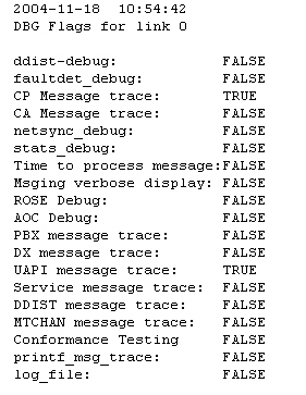
Displays the state of the DBFLAGS.
2004-11-18
10:54:42z
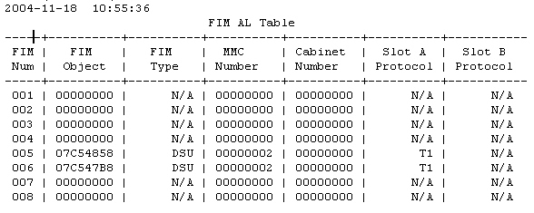
None.
Displays the information on the Fiber Interface Module.
System Response:
System Response:
