In the following example, you want to manage the bandwidth of the voice media stream between the main office in New York and the regional offices in Atlanta and Boston.
Your IT Administrator has identified the potential bottlenecks in the data pipe where the Zone Access Points (ZAPs) should be located. The Zone Access Points (ZAPs) denote where you need to measure the bandwidth between the zones. The IT Administrator has assigned the following bandwidth limits for the voice media streams through the ZAPs as follows:
|
ZAP Label |
Bandwidth Limit |
|
Atlanta-New York (ZAP ID 1) |
500 kBits/s |
|
Boston-New York (ZAP ID 1) |
1024 kBits/s |
The ZAP ID represents the number of ZAPs and the paths between each set of zones. In the example below, there is only one ZAP between each branch office zone. Therefore, both ZAPs have an ZAP ID of 1:
Atlanta-New York (ZAP ID 1)
Boston-New York (ZAP ID 1)
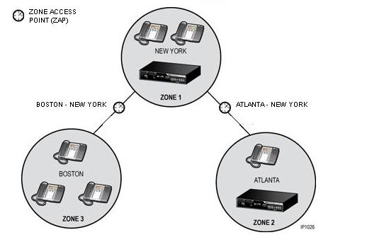
In this example, you choose to manage both ZAPs from the 3300 ICP that is located in the New York office. The following diagram shows a physical representation of the voice network:
Simple Network - Physical Representation
Next, you create a zone tree diagram that identifies the parent zones and the zones that belong to that parent. ZAPs are represented by the tree branches that connect each zone. Use the zone tree diagram to identify where call bandwidth will be recorded.
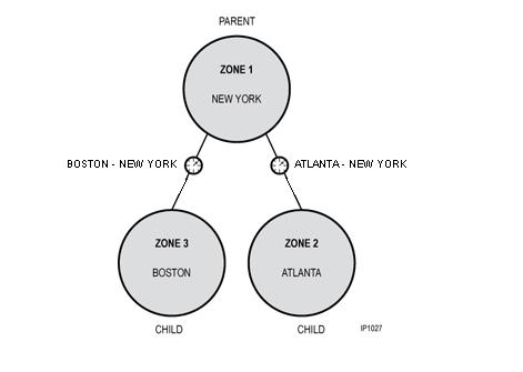
For example, a call from the Boston office (Zone 3) to the New York office (Zone 1) or vice versa will traverse ZAP:Boston-New York. The bandwidth statistics for the call will be recorded at ZAP:Boston-New York.
A call from the Boston office (Zone 3) to the Atlanta office (Zone 2) will traverse both ZAP 1:Boston-New York and ZAP:Atlanta-New York and the bandwidth statistics for the call will be recorded at both ZAPs.
|
Zone (Tree node) |
Parent Zone |
|
1 |
None |
|
2 |
1 |
|
3 |
1 |
Using the Zone Hierarchy diagram and the bandwidth limit that you received from your IT Administrator, you program the zones and ZAPs into the Network Zone Topology form. The Network Zone Topology form essentially describes the path that the voice media travels through the network and how the zones are connected in a zone tree.
Because both zones will be managed from the 3300 ICP in the New York office, you enter "New York" in the Network Element fields for both zones.
Completed Network Elements and Network Zone Topology Forms
|
Network Elements |
|
Zone Tree Assignment |
|||
|
Name |
Zone |
|
Zone ID |
Parent Zone ID |
Perimeter Zone |
|
New York (Local) |
1 |
|
1 |
|
No |
|
Atlanta |
2 |
|
2 |
1 |
No |
|
Boston |
3 |
|
3 |
1 |
No |
|
Zone Access Point Assignment (Summary) |
|||
|
Zone Access Point ID |
Zone Access Point Label |
Bandwidth Limit (kBits) |
Network Element |
|
1 |
Atlanta - New York |
500 |
New York |
|
1 |
Boston - New York |
1024 |
New York |