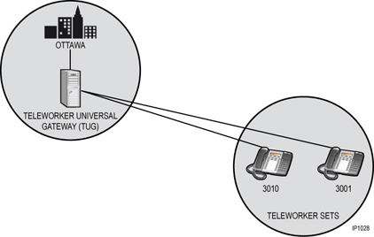
If you have Teleworker sets in your network, they are typically placed in zones outside of the local ICP 3300. The set's media flows through the Teleworker User Gateway (TUG), which is located in the same zone as the ICP hosting the sets. You would set up this ICP to manage the bandwidth for the teleworker sets. The following diagram illustrates this set-up.
Teleworker Example
You have the main office in Ottawa with the Teleworker Universal Gateway (TUG). The voice path from Teleworker 3010 to another Teleworker 3001 passes through the TUG in the main Ottawa office.
In order to properly count the bandwidth for calls between the teleworker sets located in the same zone, a "Media Path Anchor Zone" is used. The "Media Path Anchor Zone" is a zone ID field, which the user sets to the zone ID of the parent (in this case Ottawa). This indicates that the media math must past through the parent zone. Intra-zone compression is turned on so calls between the Teleworkers are compressed.
Your IT Administrator has identified the potential bottlenecks in the data pipe where the Zone Access Points (ZAPs) should be located. The IT Administrator has assigned the following bandwidth limits for the voice media streams through the ZAPs as follows:
|
ZAP Label |
Bandwidth Limit |
|
Teleworkers-Ottawa |
500 kBits/s |
|
Remote Workers-Ottawa |
1000 kBits/s |
The following diagram illustrates the zone representation and media flow for a typical Teleworker implementation:
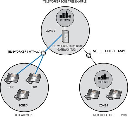
In this example, Zone 3 represents the teleworker sets and are "anchored" to Zone 2 where the Teleworker Universal Gateway is located. These teleworker sets are co-located simply for the purpose of bandwidth management. The bandwidth for a call from extension 3010 to extension 3001 must be counted twice to represent the actual bandwidth usage, i.e. the media paths associated with this call must travel to the parent zone, and back to the child zone.
A zone that has "Media Path Anchor Zone" set to parent zone ID must have a parent zone, and must have only one zone access point between that zone and the parent zone.
The programming for the media anchor zone for the above example is as follows:
|
Network Elements |
|
Zone Tree Assignment |
|||
|
Zone |
Zone Label |
|
Parent Zone |
Media Anchor Zone |
Perimeter Zone |
|
2 |
Ottawa |
|
|
|
No |
|
3 |
Teleworkers |
|
2 |
2 |
No |
|
4 |
Remote Office |
|
2 |
|
No |
|
Zone Access Point Assignment (Summary) |
||||
|
Zone |
Zone Access Point ID |
Zone Access Point Label |
Bandwidth Limit |
Network Element |
|
|
|
|
|
|
|
3 |
1 |
Teleworker-Ottawa |
500 |
Ottawa |
|
4 |
1 |
Remote Office-Ottawa |
1000 |
Ottawa |