Review the Configuration Notes.
If all the elements in your network are members of a single cluster, you do not need to assign PNIs to the elements. Assign a unique 1- to 7-digit PNI only if the cluster is connected in a MSDN/DPNSS network. PNI is also referred to as a Node ID.
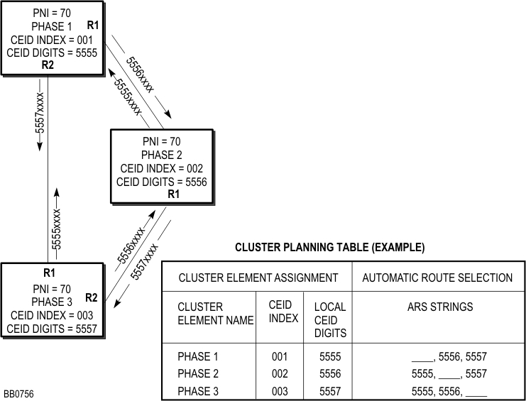
Assign a name to each cluster element. In the example shown in Figure 1 below, the elements are named Phase 1, Phase 2, and Phase 3.
Assign a unique 1- to 3-digit CEID index to each element. In Figure 1 below, the CEID indexes are 001, 002, and 003. The Cluster Element ID Index must be in the range 1 to 999.
Assign unique 1- to 7-digit CEID digit strings to each element. You use these digit strings to set up ARS routes between the elements. The CEID digit strings at each element must have the same number of digits (same length).
Complete a cluster element planning table (see below) for the cluster. For each element, enter the CEID digits of the remote elements in the ARS Strings field of the table. Figure 1 provides an example of how to complete a cluster element planning table.
Assign a unique Feature DN for each element. We recommend that you set each local Feature DN similar to its element's CEID digits. For example, if the local CEID digit string is 5555, and your cluster uses 4-digit extension numbers, set the Feature DN for that element to 1555. Then if you have to debug trace messages across the cluster, it will be easier to identify the message destination.
If your network or cluster includes 3300 ICP systems that have Release 6.0 or later software, see System Data Synchronization for information on how to synchronize system data.
|
Cluster Elements |
Automatic Route Selection | |||
|
Cluster Element Name |
CEID Index |
Local CEID Digits |
Feature DN |
ARS Strings |
|
|
|
|
|
__, __, __, __, __ |
|
|
|
|
|
__, __, __, __, __ |
|
|
|
|
|
__, __, __, __, __ |
|
|
|
|
|
__, __, __, __, __ |