This feature allows individual digital trunks to be assigned to line keys on multiline telephone sets. The user can select a specific trunk for the purpose of originating a call or may answer an incoming call which appears on the appearance of that trunk. To originate a call, the user presses the appropriate line key and dials the desired number (no dial tone is returned). To answer an incoming call, the user presses the line key which has "ringing indication". See Trunk Select - Direct for more information.
Distinctive ringing allows station users to distinguish between an internal and an external call by identifying the associated ringing pattern. Similarly, calls carried across T1 or CEPT channels can be identified as being from an external trunk via a T1 or CEPT channel. A "Calling Line Category" indication is included in the messaging to allow the system to determine the audible ringing type to be given. One of these types of ringing pattern is given:
Internal, for incoming on-net calls (industry standard or multiline sets, or dedicated analog or digital trunks).
External, for off-net calls (CO trunk, DID trunk) and calls from the attendant.
Programmable internal or external, for incoming calls from analog tie trunks (MSAN/APNSS and MSDN/DPNSS only). See System Options form for more information.
When a station which has Do Not Disturb enabled is called by a party on another system of an MSAN or MSDN network, Do Not Disturb tone (and a "Do Not Disturb" message if the calling station has display capabilities) is returned to the calling party. Camp-on or transfer to busy is not possible to a station which has Do Not Disturb activated.
See Do Not Disturb in the Features Reference for conditions, programming, and operation.
This feature allows users of Mitel display telephones to view callback messages that have been set on their extension. The called telephone extension is sent a message containing the caller's name and telephone number, and this information may be used to call back the original caller without having to dial the number. With this feature package callback messaging is extended across an MSDN/DPNSS or MSAN/APNSS network.
DPNSS callback messaging must be supported by both the originating and the terminating systems.
The ARS Node Identities form must be properly completed in order for this feature to function in a network.
The actual digits that must be dialed to reach another node in the DPNSS network must be programmed in the ARS Digits field of the ARS Node Identities form. If alternative digits should be dialed to reach a particular node, it must be programmed as a separate entry. Up to 5 Local Node Identifiers may be programmed for the local system, and up to 50 Remote Node Leading Digits entries must be programmed for the remote systems in the network.
See Callback Messaging in the Features Reference.
A Busy Lamp Field (BLF) allows the status
The key associated with the lamp will act as a Direct Station Selection (DSS) key, allowing the user to direct calls based on the call states of the set hosting the lamp and the device or group being monitored.
The monitored device may be on the same system, or another system, within the same cluster. This feature description deals in particular with information regarding DSS/BLF in a clustered environment. See DSS/BLF in the Features Reference for general information.
A device or directory number may not exceed a total of 16 local and remote busy lamp appearances.
It is recommended that no more than four remote systems carry busy lamp representations of the same device. Exceeding this recommended limit may cause BLF performance to deteriorate due to drastically increased real time updating requirements.
If the line is a multicall line, a busy indication signifies that all multicall group members are busy. A ringing indication signifies that at least one group member is ringing. An idle indication signifies that at least one group member is idle. A Do Not Disturb indication signifies that all group members' sets are in DND.
Multiline sets and associated PKMs are limited to one busy lamp per monitored directory number. There is no limit on the number of buttons which may be configured as DSS/BLF appearances on a particular set.
When a system is initialized in a single or clustered environment, local busy lamps will indicate the initial state of the monitored device. Remote busy lamps are updated upon the first call activity involving their respected monitored device.
In a clustered environment, busy lamps are not automatically refreshed upon inter-system trunk recovery. See the BLF REFRESH maintenance command for more information.
A host set's busy lamps are refreshed upon set recovery.
In a single system environment, busy lamp indications do not automatically change as a result of an activity switch. Busy lamp indications are updated upon the next call activity by their respective monitored devices. If a DSS key is used prior to call activity by the monitored device, the monitored device's status is re-evaluated and the DSS key acts on the new status.
In a clustered environment, if a receiving system switches activity, busy lamp indications are not automatically updated as a result of the activity switch. Busy lamp indications are updated upon the next call activity by their respective monitored devices on the broadcasting system(s). If a DSS key is used prior to call activity by its remote monitored device, the device's status is assumed to be idle/no DND and the DSS key acts on this status.
See Parameter Defaults for the maximum number of busy lamp groups that may be monitored.
See DSS/BLF for instructions on how to program local busy lamps. To program busy lamps in a clustered environment:
In the "Monitored Device" field of the Remote Busy Lamps form, enter the directory number of a local monitored device or broadcast group.
In the "Remote Host Set Directory Number" field of the same form, enter the directory numbers of remote sets or PKMs that will host busy lamps monitoring the local device or group. Enter data for all local devices or groups monitored by remote lamps.
In the Multiline Set Keys form, assign a local directory number to be monitored by the appropriate key number. A directory number must already exist in the system before a key and busy lamp are programmed to monitor it. Attempting to commit the form when an unknown directory number or a directory number that translates to an ARS destination has been specified will result in the error message "Directory Number is invalid".
In the Multiline Set Keys form, assign a line type to the key number. For regular DSS/BLF operation, select "dss/busy lamp". To allow secretarial transfer from the key, select "secretarial".
In the Multiline Set Keys form, assign a ring type to the key number. Ring type must be "ring" or "no ring". Selecting "ring" will cause the set hosting the busy lamp to issue a single burst of ringing when the lamp first indicates ringing state.
Note: The Remote Busy Lamps form can be used to locate all local and remote system busy lamps monitoring a device.
Busy lamps and associated DSS keys operate in the same way whether monitoring local or remote directory numbers or devices. See DSS/BLF for more information on busy lamp appearances and DSS key operation.
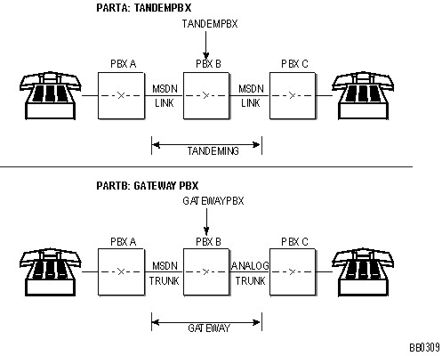
The principle function of a gateway system (see a gateway configuration) is to interconnect an incoming MSAN/MSDN traffic channel with an outgoing analog trunk, and vice-versa. Since the analog trunk is not capable of passing MSAN/MSDN information, the gateway system must fulfill the role of an end system by supplying PBX A with all the information required to complete the call. The directory number of the called station, normally returned to the originating system, is unobtainable in a gateway configuration. Only the identity of the analog trunk is returned. However, this information is for system (PBX A) use only. When the call is originated from an attendant console or a display telephone, the dialed digits displayed during call setup are replaced by the trunk number or programmed trunk label of the local traffic channel and a call time display.
Gateway Configuration